


Programming a Tamiya Microcomputer Robot
micro:bit is a registered trademark of Micro:bit Educational Foundation.
This page features basic information on programming a Tamiya Microcomputer Robot product. The information provided is related to the use of the free online MakeCode editor.
Before getting started, it is strongly recommended that you familiarize yourself with the BBC micro:bit and MakeCode editor using resources such as the tutorials provided on the MakeCode editor website, and the information provided about the BBC micro:bit at https://makecode.microbit.org/reference.
Please note that Tamiya is not liable for damage or loss of function which occur after customization of the BBC micro:bit programs. Additionally, Tamiya is not able to respond to specific questions regarding creation of programs, nor regarding the MakeCode editor
General FAQs
Q. How do I install a program onto the Microcomputer Robot?
A. Connect your BBC micro:bit and PC via Micro USB cable, and follow the steps shown on the BBC micro:bit resources and information page.
Q. How do I modify a Microcomputer Robot program?
A. The free online MakeCode editor is recommended. Visual programming uses different combinations of blocks to program the robot.
Q. How do I reinstall the pre-installed Microcomputer Robot program?
A. See the information on the BBC micro:bit resources and information page.
Q. Where can I find other sample programs for the Microcomputer Robot?
A. A selection is available on the BBC micro:bit resources and information page.
Q. Is there information about the individual blocks that appear in the programs for download from the Tamiya homepage?
A. Yes. In the MakeCode editor, click on the speech bubble icon in the top left of blocks which have one for a simple explanation of its purpose.

-

1. Turn off the model using the switch on the robot, and connect the BBC micro:bit to your PC using a micro USB cable. The PC must have access to the internet.
-

2. When connected properly, the BBC micro:bit will appear on your PC as an external drive called "MICROBIT". If it does not appear, try using a different micro USB cable to connect the BBC micro:bit to your PC.
-

3. Download the 01_DrivingProgram hex file from this page (see above) by right-clicking the link and choosing "Save Link As" or a like command.

-

4. Check that the program has been saved correctly onto your PC.
-

5. Drag and drop the program onto the MICROBIT drive to copy it onto the BBC micro:bit.
-

üÜRemove the micro USB cable. Turn on the robot and check it moves as described in the "GET MOVING!" section on page 8 of the Microcomputer Robot (Crawler Type) instruction manual.
Controlling the Robot Remotely
If using a controller to control the robot remotely, separately sold BBC micro:bit, M parts, battery case and two R6/AA/UM3 batteries are required. To use the separately sold BBC micro:bit as a controller, download and copy onto it 02_ControllerProgram from this page .General FAQs
-
How do I install a program onto the Microcomputer Robot?
A. Connect your BBC micro:bit and PC via Micro USB cable, and follow the steps shown on the BBC micro:bit resources and information page.
-
How do I modify a Microcomputer Robot program?
The free online MakeCode editor is recommended. Visual programming uses different combinations of blocks to program the robot.
-
How do I reinstall the pre-installed Microcomputer Robot program?
See the information on the BBC micro:bit resources and information page.
-
Where can I find other sample programs for the Microcomputer Robot?
A selection is available on the BBC micro:bit resources and information page.
-
Is there information about the individual blocks that appear in the programs for download from the Tamiya homepage?
Yes. In the MakeCode editor, click on the speech bubble icon in the top left of blocks which have one for a simple explanation of its purpose.
FAQs about programming the model
-
How do I give commands for the LED display on the BBC micro:bit?
A1. Use the "show string" and "show number" blocks shown at right.

A2. The "show leds" and "show icon" blocks can also be used, with plenty of different variations.

-
How can I use the Motor Driver Circuit (mi-01) buzzer to play sounds and even melodies?
Step 1: In the "on start" block, insert the "analog set pitch pin" block and define "[P8 (write only)]". (The buzzer is assigned to the P8 terminal on the BBC micro:bit.)

Step 2: Use blocks such as "start melody" and "play tone" and alter settings as you like.

-
How do I give the Motor Driver Circuit (mi-01) motor control commands?
A. First, basic settings must be input. Then, motor movement requires commands to i) remove the brake, and ii) set the speed. Stopping the motors requires a command to apply the brake, or set the speed to zero. See the following steps.
Step 1: Basic Settings. In the "on start" block, insert the "analog write pin [P0]" block, selecting P13 and inputting the value 511. Insert one more of the same block, this time selecting P14 and inputting the value 511. Next, insert two "analog set period pin [P0]" blocks, selecting P13 and P14 for one each. Input the value 1000 in both.
These blocks define the motor driver circuit terminals on the BBC micro:bit (P13 = right and P14 = left), and set the output period.
Step 2: As noted above, you must first remove the brake before the motor can rotate. Insert two "digital write pin [P0]" blocks, selecting P15 and P16 for one each. Input the value 0 in each. This command removes the brake until you command it be applied again.

Step 3: Next, set the motor speed.
Insert two "analog write pin [P0]" blocks, selecting P13 and P14 for one each. Input a value in each to set the speed. (see the tables below for further explanation of the different terminals (P), and the speeds which different values give.)

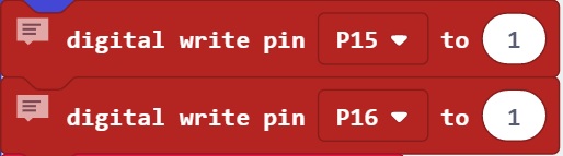
Step 4: Applying the brake will stop the model regardless of the values set for speed. Insert two "digital write pin [P0]" blocks, selecting P15 and P16 for one each. Input the value 1 in each. This applies the brake.

Other FAQs (mi-01, mi-02)
-
How do I give the Ultrasonic Sensor (mi-02) commands to measure the distance between the robot and other objects?
A signal (i2c) connection must be made between the mi-02 (address: 44) and the BBC micro:bit. The sensor sends out ultrasonic signals and measures how long they take to return. The BBC micro:bit requests data from the mi-02, which splits the data and sends it in two lots that tell the BBC micro:bit how far away an obstacle is.
The relevant commands are detailed below. Also see Tables 1 and 2 at the bottom of this section.
Step.1
First, give a command for the mi-02 to start operating. Insert an "i2C write number" block with the address 44 (the mi-02), with value 51 (start measuring), format UInt88BE (format of the data) and repeated "false". Values for address, format and repeated will be reused in all later steps.

Step.2 Insert an "i2c read number at address" block and input all other fields as in Step 1. In the "if" block, 1 means the mi-02 is measuring and 0 means it is not.

Step.3 Use an "i2c write number" block and input value 15. Input all other fields as in Step 1.

Step.4 In a "set" block, define DataH (first data lot), and insert an "i2c read number at address" block and input all other fields as in Step 3. This command tells the BBC micro:bit to receive the first lot of data on time taken for the signal to reflect.

Step.5 Use an "i2c write number" block and input value 14. Input all other fields as in Step 1.

Step.6 In a "set" block, define DataL (second data lot), and insert an "i2c read number at address" block. Input all other fields as in Step 4. This command tells the BBC micro:bit to receive the second lot of data on time taken for the signal to reflect.

Step.7 If neither lot of data is 0, data will be successfully read.
-
How do I check whether data from the mi-02 Ultrasonic Sensor is being received accurately?
The two lots of data can be totalled in both the mi-02 and the BBC micro:bit, and then compared via command. See the following steps.
Step.1 Insert an "i2C write number" block with the address 44 (the mi-02), with value 16 (add first and second lots of data), format UInt88BE and repeated "false".

Step.2 Use an "i2c read number at address" block and input value DataH + DataL.

Step.3 The totals from the mi-02 and BBC micro:bit are compared and "OK" (numbers match, data is accurately received) or "NG" (don't match) is displayed on the LED screen.

-
What are the mi-01 and mi-02 specifications?
Motor Driver Circuit (mi-01)
Input Voltage: 3V (R6/AA/UM3 batteries x2)
Current Consumption: 500mA (50mA when not operating)
Input Connectors: BBC micro:bit, Switch Input, Motor Output x2, I2C (3.3V) x2, I2C (power, current)
Ultrasonic Sensor (mi-02)
Input Voltage: 3.3V
Frequency: 40kHz Angle of Operation: 30° either side (approx.)

-
Can I use different motors in the Microcomputer Robot?
No. Please only use motors of the same type as those provided in the kit when purchased new.
Other FAQs (remote control)
-
How can I control the robot remotely?
Two BBC micro:bits can be set to act as a controller and receiver. This requires the controller to send data, which the receiver in the robot gets and translates into motion. You can define what controller actions send what commands to the robot.
The following command needs to be setup for both controller and receiver. In the "on start" block, insert a "radio set group" block, and ensure that the group number is the same for controller and receiver. All BBC micro:bits with this group number will be able to communicate.

Step.2 To send data from the controller, use one of the "radio send number", "radio send string" or "radio send value" blocks shown.

Step.3 To receive data on the receiver, use the one of the three "on radio received" blocks shown that corresponds to the block used in Step 2.

Step.4 Received data can be removed and used as a value by dragging the field out of the block as shown.

-
How can I make separate connections between the robot and different controllers?
This can be done by inserting "radio set group" blocks with different numbers that correspond with those set for different controllers. Under factory settings, the group is set to 37.

